May 3, 2024
July 7, 2022
June 24, 2022
January 24, 2022
October 28, 2021
July 8, 2019
November 26, 2018
September 22, 2017
June 9, 2017
September 27, 2017
July 24, 2017
September 22, 2017
September 27, 2017
November 26, 2018
January 30, 2019
It’s been known for a very long time that thermal conductivity is plays a large role in many aspects of science and engineering. George Frederick Charles Searle, a professor at Cambridge, frustrated that there was no experiment that could easily be demonstrated and understood by his undergraduate students that would be a tangible example of thermal conductivity. He designed an experimental method that could be reproduced many times over without needing to change the equipment; he published a paper detailing this design in 1905. Now named the Searle’s bar method, it is not exactly considered convenient by today’s higher standards, but it is still a very interesting and very tangible way to learn about thermal conductance.
In 1954, Dr Searle unfortunately passed away. This let the Phillip Harris company to begin to sell a commercialized version of the experiment, which allowed undergraduates, and other curious people around the world to see with their own eyes how the thermal conductivity of a material changes its interactions with the world. The product is no longer being sold today, likely due to the recent prevalence of cheaper experiments
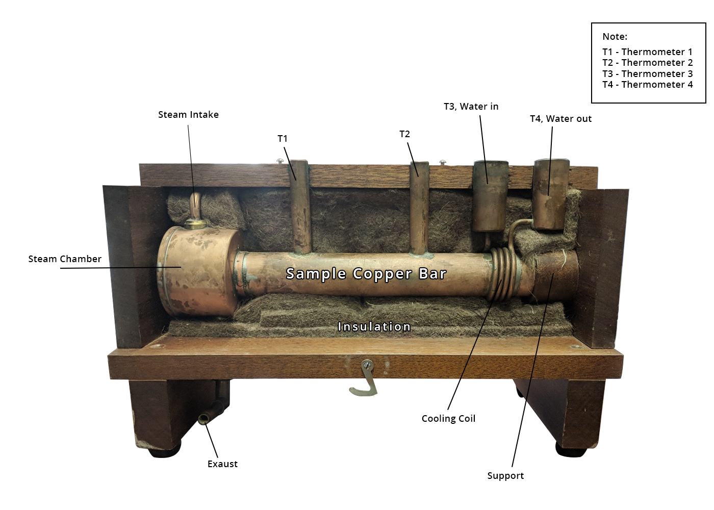
The main body of the Searle’s bar apparatus is a uniform and cylindrical bar made of a metal that has a high thermal conductivity that you would like to measure, usually this is copper. The bar is heated on one side by any device that can provide a reliably steady heat flow and cooled on the other end by a copper tube of cool, slowly running water coiled around the bar.

Searle’s Experimental Setup
In the original designs, the end of the bar to be heated was air-tightly fitted to a hole in a hollow copper cylinder, called a steam chamber, of a larger radius than the bar, in which steam from a small boiler was passed through, and which heated the metal along the way. The boiler is just a metal can that can be given a lot of heat by a stovetop, or a hot plate, with a lid that funnels the steam produced by the boiling into a pipe that leads into the top of the steam chamber, where it imparts some heat into the sides of the chamber and the bar, and eventually the steam is pushed out another pipe at the bottom leading away from the device, then lets the steam escape as exhaust.
This method of heating the metal is more reliable than directly heating with other pieces of metal, because it is difficult to keep that metal at constant temperature, but the steam chamber is designed to keep the steam at a constant pressure, and therefore temperature. A more modern way of heating the end of the bar would be with a filament with a known resistance coiled around the end of the bar with an electrical current passing through, caused by a known voltage.

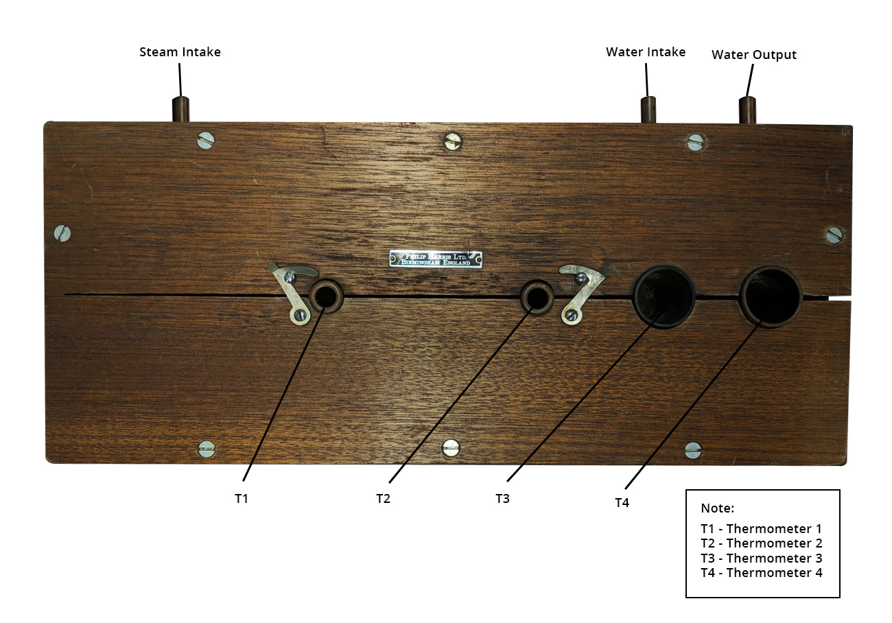
There must be a thick layer of insulation around the bar, steam chamber and the water pipe to reduce any exchange of heat that isn’t at the ends of the bar, but there must be two holes in the insulation to insert thermometers that will rest against the metal and will be taken as T1 and T2. For the best accuracy, there should be small holes (or grooves) in the metal bar as well, for the thermometers to fit into, and if it ends up as a loose fit, then a viscous material with a huge thermal conductance called thermal paste can be put in the holes first.
If you have the means, however, you may wish to add walls around the places to put the thermometers made of the same metal as the bar. This will let you avoid the use of thermal paste, as it is difficult to clean, and instead fill those walls with a water bath for the thermometers. This will work almost as well as the thermal paste because the small amount of water will be in contact with a large surface area of the metal, and will therefore rise to the temperature of the metal very efficiently. The lack of needing to clean the apparatus would result in more re-usability.
The holes should be close to either end of the bar, for convenience, and will allow the user to know the temperature difference along the bar. Two more thermometers will be placed in the copper coolant pipe, before and after its coil, to measure the temperature of the water before and after it had time to absorb heat from the bar. These will be T3 and T4. The water intake can be fed with any steady source, and the water leaving the system can be directed down a drain, as it is not needed.
Heat transfer between two points in a material via thermal conduction can be calculated as
\[ \frac{Q}{t} = \frac{kA(T_{point\, 1}{-}T_{point\, 2})}{(distance\, between\, points)} \]
In the case of Searle’s bar, Tpoint 1 = T1, and Tpoint 2 = T2, the distance in question is d, t is the time, A is the cross – sectional area, and k is the thermal conductivity.
The power, or heat per time, put into the water is calculated by
\[ \frac{Q}{t} = cm(T_{final}{-}T_{initial}) \]
Where, Tfinal = T3, and Tinitial = T4, and c = the specific heat of water, and m = the mass of water per second going through the pipe.
In the Searle’s bar method, a metal bar is being continuously heated at one end and cooled continuously at the other. Eventually, a phenomenon known as dynamic thermal equilibrium takes place, meaning that there is a temperature gradient along the metal bar, but there is no change in temperature anywhere along it. Doing measurements of heat on a state of dynamic thermal equilibrium is known as dynamic calorimetry. This state can occur because there is a flow of heat through the system, and the amount of heat entering the system at any time is equal to the amount leaving at that time. In this case, our system is a metal bar with a high thermal conductance, so the flow of heat through it will not only be continuous in time, but the change in heat per time would be exactly constant, if our bar had no impurities, but for our purposes, the error caused by impurities will be low enough to ignore. For this reason, we could put the thermometers T1 and T2 anywhere along the bar, and as long as we know the length of space between them, d, our known equation for heat transfer per second should not change, however, putting the thermometers too close together might result in equipment error, meaning that some heat would pass through the insulation from one thermometer to the other.
We also know how to find the amount of heat given to a known mass of water, if we know the temperatures of the water before and after the heat transfer, which is what T3 and T4 give us. So, if we know the mass of water flowing over the bar per second, then we can find the amount of heat being transferred from the bar to the water per second. From what we discussed about dynamic thermal equilibrium; we know that the amount of heat leaving the bar over a time will be equal to the heat transfer anywhere along the bar during that time. This is what makes things easy, since we already know how heat transfer through a material is related to its thermal conductivity.
Before you turn anything on, make sure you know the dimensions on the bar you will be using. You will need to know its diameter D, to find its area A, as well as the distance between the two thermometers.
You can find this quantity by turning the water on, then catching some in a pre-weighed beaker while timing it with a stopwatch. The mass of the water in the beaker can then be found by placing it on the scale and subtracting the weight of the beaker. Then divide by the number of seconds you measured, and that will be the mass flowing past a spot in the pipe every second.
The system doesn’t enter a dynamic thermal equilibrium immediately, so you will have to wait for a while, keeping an eye on the thermometers, T1 and T2. When there is very little change occurring, (less than 0.5 degrees Celsius over 5 minutes), you can treat the system as you would in an equilibrium state. When this happens, take the measurements from T1, T2, T3, and T4.
Heat transfer per second between two points in a material via thermal conduction can be calculated as
\[ \frac{Q}{t} = \frac{kA(T1-T2)}{d} \]
And the heat being absorbed by the water can be found by
\[ \frac{Q}{t} = cm(T3-T4) \]
These can be combined and rearranged to give us our thermal conductivity
\[ k = \frac{cmd}{A} \frac{(T3-T4)}{(T1-T2)} \]
Remember that the area of a face of a cylinder is pi times the square of the radius of the cylinder, r; A = π r2.
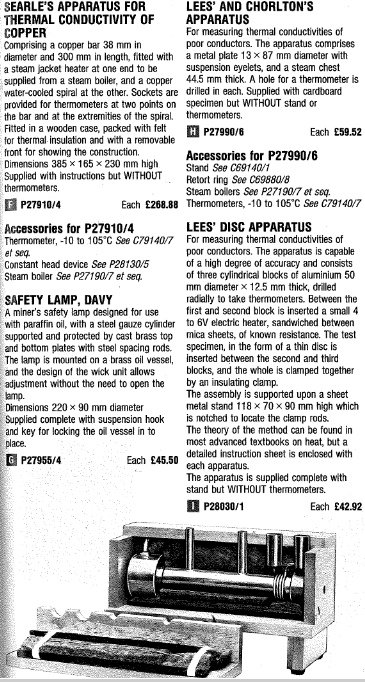
A selection from a Philip Harris catalog with the original searle’s bar apparatus.

Dr Searle’s before mentioned paper, published in 1905, can be found in Philosospical Magazine, series 6, section 9, pages 125-129: https://www.tandfonline.com/doi/pdf/10.1080/14786440509463260?needAccess=true
The Royal society: https://royalsocietypublishing.org/doi/pdf/10.1098/rsbm.1955.0018
Author: Cole Boucher, Junior Technical Writer at Thermtest