
January 13, 2016
The pursuit of thermal conductivity knowledge has led to the development of an array of measurement techniques in the past century. One of the lesser known methods is the Guarded Comparative Longitudinal Heat Flow Technique, which adheres to ASTM Standard E1225. This method is a steady-state, comparative technique that determines the thermal conductivity of a solid specimen through the use of two identical reference pieces with known thermal properties. The approved thermal conductivity detection range of this technique encompasses 0.2 to 200 W/mK, and measurements can be performed between 90K and 1300K.
The set up required for accurate thermal conductivity measurement through this method is illustrated in Figure 1. The sample to be tested is pressed between two reference samples of equal size and shape and a known thermal conductivity. A heater is placed on top of this sample stack, and creates a heat flow through the samples. A liquid cooled heat sink at the bottom of the stack removes excess heat and controls the average temperature. Force is applied to the top of the stack to ensure excellent thermal contact between the test and reference samples. Insulation is placed on either side of the sample set up to ensure that no heat is lost radially.
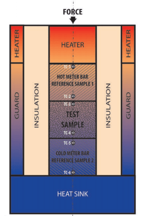
Figure 1. Diagram illustrating the sample set up used for thermal conductivity measurement with the Guarded Comparative Longitudinal Heat Flow technique.1
Thermocouples are placed in multiple locations during measurement (Figure 1); including between the top reference sample and the heat sink, the top reference sample and the specimen, the specimen and the bottom reference sample, and the bottom reference sample and the heat sink. All measurements are taken after the sample has reached equilibrium to fulfill the requirements of the steady state set up. Thermal conductivity is determined by calculating the heat flux in the reference samples, which act as meter bars, and the temperature gradient through the test sample (Figure 2).
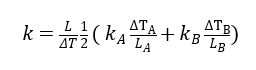
Figure 2. Equation used to calculate the thermal conductivity of the test specimen using the Guarded Comparative Longitudinal Heat Flow technique.2 Where ΔTA is the temperature change across the top reference sample, LA is the length of the top reference sample, ΔTB is the temperature change across the bottom reference sample, LB is the length of the bottom reference sample, kA and kB is the thermal conductivity of the reference samples, and L and ΔT are the length and temperature gradient in the test sample.
The Guarded Comparative Longitudinal Heat Flow technique has been in use since the 1930s, however extensive work went into further development in the 1950s and 1960s. Ballard et al. (1950) used a simplified version of the method to measure the thermal conductivity of poorly conducting materials. Francl and Kingery (1954) expanded upon the method when measuring heat flow through 1 inch cubed samples, and paid extra attention to preventing heat loss and attaining a linear heat flow. The 1960s produced additional improvements to the design. In 1965, Mirkovich tested the thermal conductivity of five different materials using the technique and investigated the accuracy of the system. He determined that this method provided accurate results, however pinpointed a weakness in properly guarding the heat of the samples as the major drawback.
This method was officially certified by ASTM in 1989 under standard E1225. This standard was reviewed and revised in 2004. Two major findings of that particular study outlined how to classify homogenous materials for use in the technique, and proper sample sizes needed for heterogeneous testing. Thermal conductivity cannot vary by more than 5% through changes in thickness or cross sectional area to be considered homogenous. For composites and heterogeneous samples, the sample size must be wider and thicker than a single layer, preferably by 20L, where L is the thickest layer thickness. Accuracy of the technique is placed at better than 5%.
Previous reviewers of this method have noted that it is not commonly used. However, recent work has focused on expanding the temperature range that the technique can be applied to. In 2011, a group of researchers created a slightly adapted system based on ASTM E1225 to measure the thermal conductivity of nuclear fuel compacts at temperatures higher than 1200K. Therefore, despite the fact that many in the field prefer other methods, the Guarded Comparative Longitudinal Heat Flow technique is still evolving to meet testing requirements of modern materials.
Sources
ASTM E1225-13, Standard Test Method for Thermal Conductivity of Solids Using the Guarded-Comparative-Longitudinal Heat Flow Technique, ASTM International, West Conshohocken, PA, 2013, www.astm.org
Ballard, S., McCarthy, K., and Davis, W. 1950. A Method for Measuring the Thermal Conductivity of Small Samples of Poorly Conducting Materials such as Optical Crystals. Review of Scientific Instruments, 21, p. 905.
Francl, J., and Kingery, W. D. 1954. Apparatus for Determining Thermal Conductivity by a Comparative Method. J. American Ceramic Society, 37.
Gross, K.J., Hardy, B. 2013. Recommended Best Practices for Characterizing Engineering Properties of Hydrogen Storage Materials. H2 Technology Consulting Report. Available at: https://www1.eere.energy.gov/hydrogenandfuelcells/pdfs/best_practices_hydrogen_storage_section_6.pdf
Mirkovich, V. 1965. Comparative Method and Choice of Standards for Thermal Conductivity Determinations. J. American Ceramic Society, 48(8), p. 387-391.
Morris, R., and Hust, J. 1961. Thermal Conductivity Measurements of Silicon from 30 to 425 C. Physical Review, 124(5), p. 1426-1430.
https://inldigitallibrary.inl.gov/sites/STI/STI/4953364.pdf
Photo Sources:
1- https://www1.eere.energy.gov/hydrogenandfuelcells/pdfs/best_practices_hydrogen_storage_section_6.pdf
2- Kaviany, M. 2002. Principles of Heat Transfer. John Wiley and Sons (New York). pg 236.