Join us at the International Thermal Conductivity Conference (ITCC) and the International Thermal Expansion Symposium (ITES).
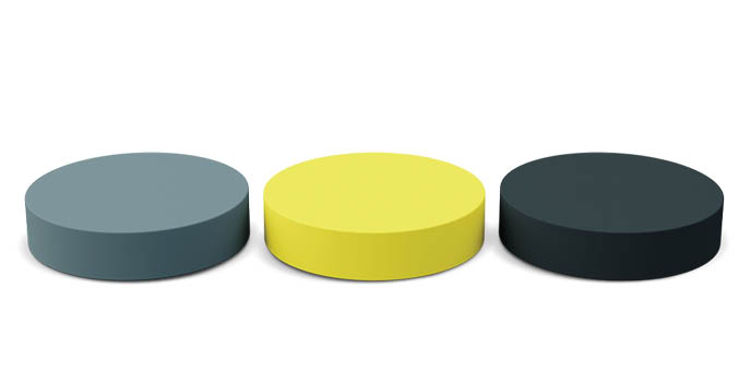
The GHFM-01 Guarded Heat Flow Meter is designed to test the thermal resistance and thermal conductivity of both homogeneous and heterogeneous materials.
Best For Metals, Polymers, Composites, and Pastes
Standard Test
Method
Temperature
Range

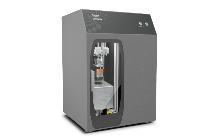

The Guarded Heat Flow Meter (GHFM-01) follows ASTM E1530-19 for testing thermal resistance and thermal conductivity of solids, such as metals, polymers, composites and paste from -20 °C to 310 °C. The Thermtest proprietary testing stack, replaces the traditional pneumatic movement with advanced motor control, which allows automated control of testing sample thickness, force or pressure applied.
The advanced GHFM-01 is a primary measurement of thermal resistance—thermal conductivity for solids, such as metals, polymers, composites and paste. Specifically, the calculation of thermal conductivity from measurement of thermal resistance is the most accurate method of testing the true thermal conductivity of heterogeneous materials. The steady-state measurement of thermal resistance represents the full sample thickness and mature heat transfer properties.
According to the method, the sample is subjected to a steady-state through-thickness temperature gradient. The thermal conductivity of the sample is obtained by measuring the temperature difference across it, and one additional temperature.
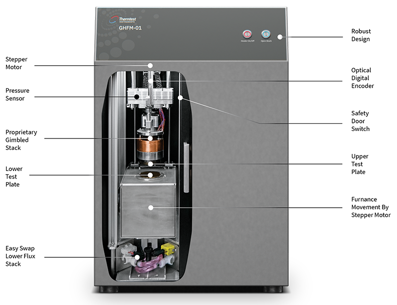
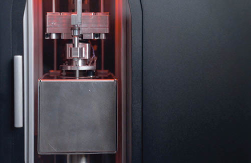
The testing stack is made up of a heater – upper plate, with integrated temperature sensor and heat sink—lower plate with integrated temperature sensor on each side of the sample. Additional temperature sensors are placed near the top and bottom surface of the sample.
Once steady-state temperature across the sample is achieved, the Fourier law equation can be applied. The ratio RS (m2•K/W), equal to the thickness of the sample, d (m) to its thermal conductivity, λ (W/m•K), can be obtained from the temperatures measured:
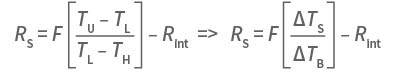
The above equation is linear in form, and is the working equation of the instrument. Constants F (m2•K/W) and Rint (m2•K/W), can be obtained by calibration of the instrument. To this effect, calibration samples of known thermal conductivity and hence, thermal resistance, are employed. Calibrated results for thermal resistance and thermal conductivity are reported.
Following international standards, the GHFM-01 is designed for testing both homogeneous and heterogeneous materials.
| Materials | Metals, Polymers, Composites, and Pastes |
|---|---|
| Type of Sensors | Thermocouples (x6) |
| Applications | General Testing |
| Direction | Through-Thickness |
| Thermal Conductivity Range* | 0.1 to 100 W/m•K |
| Measurement Time | 40 to 60 min |
| Accuracy | ± 3% |
| Repeatability | ± 1 to 2% |
|---|---|
| Plate Temperature Range** | -20 to 310 °C |
| Pressure | Automated up to 7 KPa (55 psi) |
| Sample Diameter | 50 to 50.8 mm |
| Sample Thickness | Up to 25 mm | Thin-films down to 0.1 mm with optional Software |
| Standard | ASTM E1530-19 |
*Above 60 W/m·K, the material should be a minimum of 12.5 mm thick
**Chilled circulator included with each system
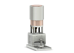
No tools are required to change the lower flux module, which forms a calibrated heat flux transducer. Housing multiple thermocouples to monitor temperature for confirmation of steady state condition of the temperature gradient across the sample is achieved.
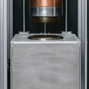
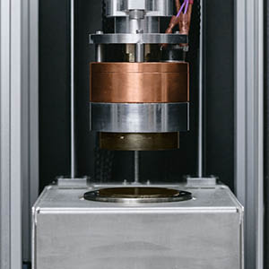
Optimally selected heaters cooled by heat exchangers matched with thermocouples, which have a resolution of 0.01 °C are positioned in the upper and lower stack are used to accurately control plate temperatures. Lateral heat loss across the sample thickness is minimized with the use of a guard oven. Upper and lower plate along with guard oven temperatures are fully controlled by the convenient GHFM-01 Software.
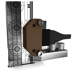
Accurate sample thickness is required for determining thermal conductivity of a material from the measurement of thermal resistance. The GHFM-01 features a proprietary gimble design, which has the advantage of either an automatic determination of sample thickness, for rigid materials, or a user defined sample thickness, force or pressure applied for compressible materials. Sample thickness is measured using digital optical encoder technology, ensuring the most accurate (± 0.025 mm) measurement of sample thickness.
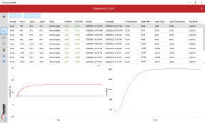
The GHFM-01 offers a feature packed Windows based software included with each system. The simple to use software offers unlimited automation steps of temperature along with thickness force or pressure settings. Basic testing and calibration steps are fully automated, as well as additional functions like saving, exporting, and printing of measurement results.
For rigid materials, the GHFM-01 plates automatically clamp together for optimum sample contact. When testing compressible materials, the desired height, force or pressure (up to 80 kg, 379 KPa – 55 psi) applied may be set in the software and the plate will automatically stop once desired sample height or pressure is achieved.
All conditions of calibration, such as management of reference materials, temperature steps and pressure are fully automated with the GHFM-01 software. Verification of calibration is performed through built in validation routines.
To measure thin films according to ASTM-E1530-19, a layer approach must be used. By stacking different numbers of layers of a material of known thickness, a linear fit can be created. As resistance is correlated with thickness, each different thickness (different number of layers) of the sample will have a proportional resistance. The thermal resistance is then plotted against the known thickness. The inverse of the slope of this linear fit is the resulting thermal conductivity of the material. Using the Thermtest GHFM-01 software, this is easily calculated with minimal user input.
Mylar is a polyester film that is also known as BoPET or biaxially-oriented polyethylene terephthalate. This film is commonly used in the aviation, electronics, and food industries due to its stability and insulative properties. For this experiment, the thickness of one layer of Mylar was 0.055mm, and the minimum number of layers was 5.

| Thermal Resistivity (Slope of the Line) | 6.275 m•K/W |
| Thermal Conductivity (Inverse of Slope) | 0.159 W/m•K |
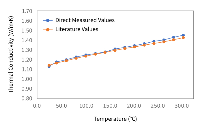
Demonstrating the performance of the GHFM-01, measurements on Pyrex 7740 were made up to 300 °C and compared to literature values. Accuracy of all results < 2%.
| Temperature ( °C) | 25 | 40 | 60 | 80 | 100 | 120 | 140 | 160 | 180 | 200 | 220 | 240 | 260 | 280 | 300 |
|---|---|---|---|---|---|---|---|---|---|---|---|---|---|---|---|
| Direct Measured Values | 1.134 | 1.172 | 1.192 | 1.223 | 1.246 | 1.261 | 1.280 | 1.307 | 1.325 | 1.343 | 1.361 | 1.386 | 1.401 | 1.426 | 1.451 |
| Literature Values | 1.143 | 1.164 | 1.190 | 1.214 | 1.236 | 1.257 | 1.276 | 1.295 | 1.313 | 1.330 | 1.348 | 1.366 | 1.385 | 1.404 | 1.426 |
| Error (%) | 0.80 | 0.71 | 0.11 | 0.71 | 0.75 | 0.33 | 0.27 | 0.96 | 0.92 | 0.99 | 0.98 | 1.44 | 1.19 | 1.54 | 1.78 |
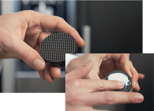
GHFM-01 samples should be 50 to 50.8 mm in diameter. The top and bottom surfaces should be flat and parallel. A thin layer of contact paste is added to the top and bottom of the sample surface.
Approximate Time: 1 minute
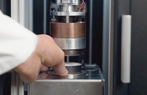
Sample then can be loaded into the testing stack. For rigid materials, upper stack will close to a default pressure. For soft materials, the user can define a specific pressure or required thickness. Pressure and thickness testing parameters can be controlled within the testing schedule.
Approximate Time: 1 minute
Using the GHFM-01 Software, the user is able to schedule unlimited temperature steps up to 300C. Internal red backlight signals testing in progress.
Approximate Time: 40 to 60 minutes
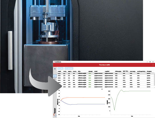
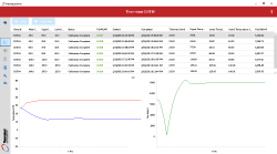
Temperatures from upper and lower plates are monitored by the GHFM-01 software for temperature stability. Measured thermal resistance and calculated thermal conductivity results are tabulated and available for export to excel. Internal blue backlight signal testing is complete and stack safe to touch.
Approximate Time: 1 minute
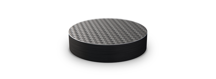
When testing anisotropic composites, the measurement of thermal resistance—thermal conductivity is ideal. Composites typically do not have repeating internal layers, making the measurement of full thickness by thermal resistance the only way to measure true thermal conductivity. A carbon fiber composite sample of 12.7 mm thickness was measured, and results summarized below.
| Mean Temperature ( °C ) | Thermal Resistance (m2K/W) | Thermal Conductivity (W/m•K) |
|---|---|---|
| 40 | 0.0252 | 0.5153 |
| 60 | 0.0229 | 0.5671 |
| 80 | 0.0213 | 0.6103 |
Measuring the thermal conductivity of a composite with added layers increases the measurement complexity. Transient methods designed to measure the thermal conductivity of well organized anisotropic materials, are not well suited for non-repeating layered structures.
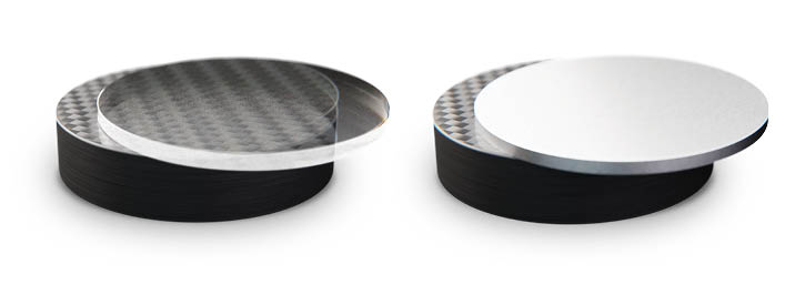
Layers of pyrex and stainless steel were added to the anisotropic carbon fiber composite sample of 12.7 mm thickness. For the full thickness, thermal resistance and thermal conductivity were measured at a mean temperature of 40 °C, and results summarized below.
| Added Layer to Carbon Fiber Composite | Thickness (mm) | Thermal Resistance (m2K/W) | Thermal Conductivity (W/m•K) |
|---|---|---|---|
| Pyrex | 3 | 0.0264 | 0.5680 |
| Stainless Steel | 2 | 0.0251 | 0.6340 |
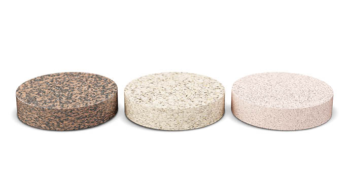
The GHFM-01 is well suited for the measurement of thermal resistance and thermal conductivity for a wide range of materials. As the GHFM method measures the thermal resistance of a sample size of 50 to 50.8 mm in diameter and thickness up to 25 mm thick, testing heterogeneous materials is possible.
With the ability to schedule desired compression or pressure, the GHFM-01 is uniquely capable of testing compressible materials like rubber and gasket materials. Using the GHFM-01 software, any variation or combination of temperature, compression or pressure is possible.
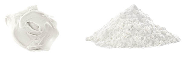
There are a wide variety of test cells available to extend the application range of the GHFM-01. These include paste, polymer – melt and powders cells.
We are happy to arrange a live demonstration for you!
